Understanding B-Rep: geometry and topology inside a CAD model
How do vertices, edges, faces and solids fit together? Boundary representation helps explain the different roles of CAD data and visualization meshes.
An engineering model must describe a shape and support operations such as intersections, Booleans, fillets and measurements. Boundary representation, or B-Rep, is an important concept in understanding solid modeling.
Geometry and topology describe a shape together
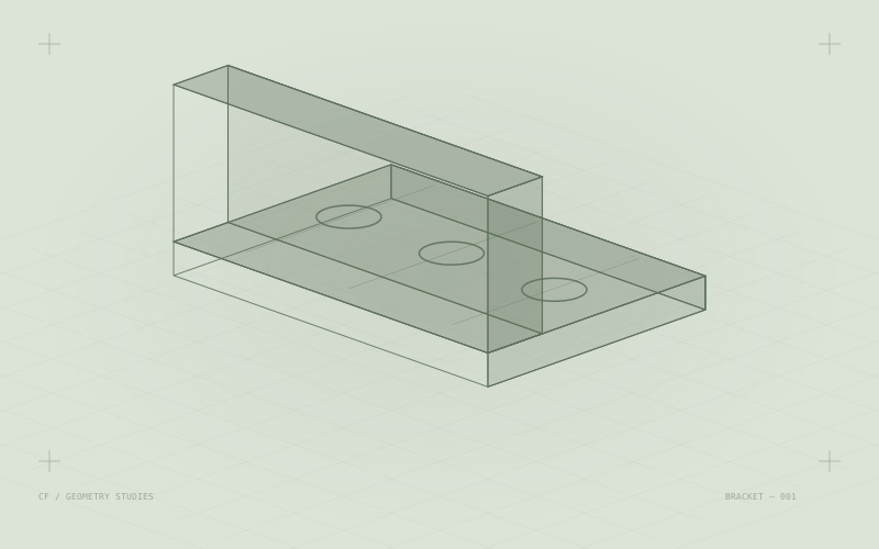
Geometry describes the positions, parameters and shapes of curves and surfaces. Topology describes how boundaries connect and how they form faces, shells and solids.
The same surface can be trimmed by different boundaries. Whether a model is closed, edge orientations are consistent and neighboring faces connect correctly affects subsequent operations.
The role of meshes
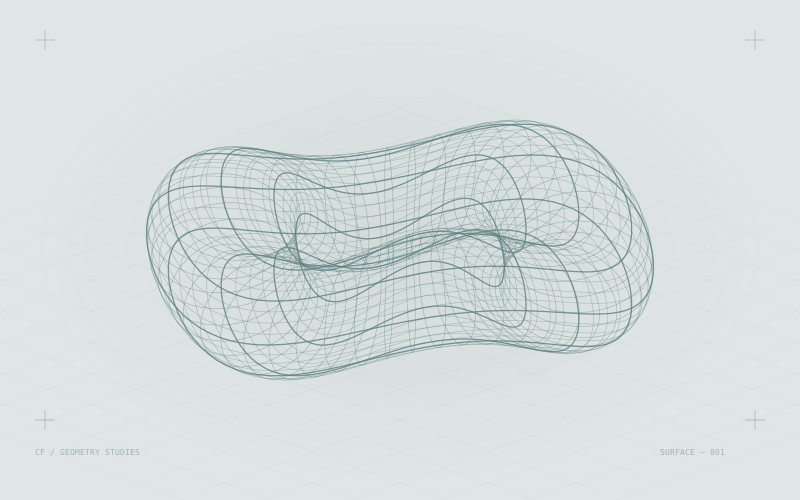
Triangle meshes work well for rendering, transfer and many numerical computations. When a display mesh is generated from a CAD solid, the discretization precision affects visual appearance and data size.
Inspecting a rendered image reveals only part of model quality. Engineering workflows also need checks on topological consistency, tolerances and critical geometric conditions.
Implications for AI CAD
A system might generate an object that looks convincing in an image but fail to deliver a solid suitable for subsequent Boolean operations. Research and product evaluations should state the output representation and use validation methods appropriate to it.
The illustration is conceptual. This is an introductory explainer; consult the geometry kernel’s documentation for specific APIs and algorithms.