Drawing-to-CAD: a workflow built around native feature history
Keep native CAD as the source of truth: build features, compare drawings, add properties, generate drawings and archive revisions, with engineering review.
Originally published by AI驱动产品设计 on October 11, 2026. This republication preserves the author's proposed architecture. Completion percentages and review-effort estimates are hypotheses, not measured productivity results or product guarantees.
One way to approach drawing-to-CAD is to ask a general model to read a drawing and produce a model in one pass. The earlier CAD Arena discussion showed why relying on an unchecked result has limited engineering usefulness.
For an output-only approach, I see three principal difficulties:
- Understanding a description does not close the dimensional loop. Ambiguous projection, datums or tolerances can leave a plausible shape with incorrect critical dimensions, hole patterns or interfaces.
- If feature history is absent, modification becomes expensive. Patterns and variants may require substantial rebuilding rather than continuation in a familiar feature tree.
- The deliverable may not fit enterprise management. Teams need revisions, permissions and PLM-compatible assets, not an isolated shape in a chat window.
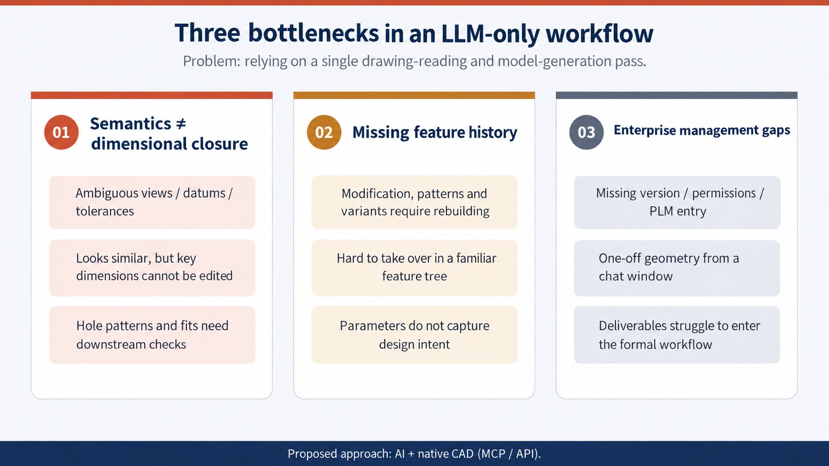
Figure 1. Concept illustration of the three risks. This is a proposed workflow argument, not evidence that all language-model approaches lack feature history.
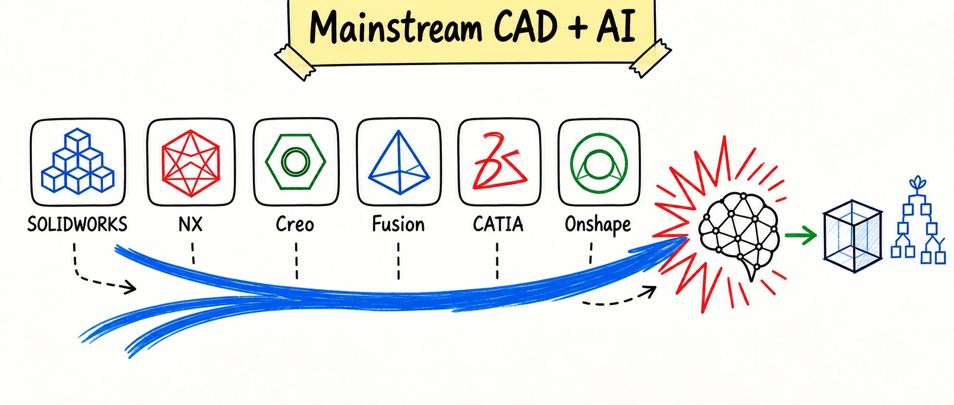
A language model can reason about drafts, but the full set of industrial constraints needs more than a first generated result. My proposed route uses established CAD methods in NX, SOLIDWORKS, Creo or Fusion, with AI assisting the work. Reconstruction should remain editable and manageable in the existing engineering environment.
1. Where AI fits
The practical architecture is AI working with mainstream CAD. Within the capabilities of each specific interface, an API or the Model Context Protocol (MCP) can expose structured information about sketches, constraints, features, parameters, dependencies and assembly context. A model can use that information to choose operations and read their results. The CAD kernel and feature history remain the source of truth.
This differs from receiving only a STEP export. An interface capable of creating sketches, adding features, changing parameters and inspecting the result supports an assistant operating within the model. A history-free solid may still need substantial reconstruction before revision and drawing workflows can continue. MCP alone does not guarantee those operations; the available tools and host API determine the boundary.
End-to-end generation that produces only a mesh or history-free solid creates difficulties when dimensions, arrays or datums change. It also has to reconnect with existing templates, material libraries and drawing conventions. The important architectural question is whether the assistant can work in the maintained engineering model, rather than simply deliver a shape.
Inputs require similar discipline. A drawing can be supplemented by photographs of a physical part to clarify form, orientation, surface appearance, wear or assembly context. Photos can reduce guessing when a view is missing, but they are not the dimensional reference. Perspective, glare, missing views and dirt still require drawing dimensions and human review.
2. A loop from native features to managed drawings
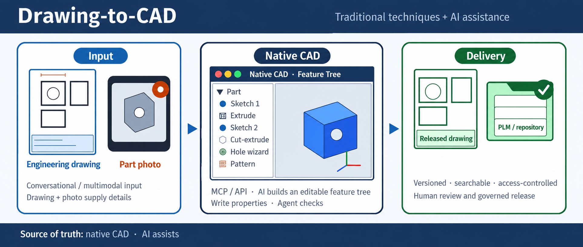
Under this architecture, I would organize drawing-to-CAD into the following stages.
Build an editable native feature history. The agent creates extrudes, revolves, holes, patterns and chamfers in the CAD system used by the team. The first version need not be perfect. As an illustrative target, even roughly 60% of the required features can be useful if the remainder can be completed in that same tree. This is not a claim of 60% time saved: a partially complete but unusable history may save little.
Compare repeatedly with the source. The first generation starts a review loop. The agent should compare views and hole locations, wall thickness and ribs, symmetry and patterns, and datum choices against the drawing and any supporting photographs. It then revises the model until it is ready for engineering review. Stopping too early turns human review back into complete reconstruction; a useful intermediate model lets the engineer inspect and finish it.
Read drawing text and populate CAD properties. Extract part number, name, material, revision, mass information and finish where specified, then save according to naming conventions. At archive scale this is as important as geometry: unstable identifiers and missing properties break retrieval, reuse, BOM generation and downstream drawing management.
Generate associative native drawings and reconcile them with the original. Create drawings from the model, then check views, sections, dimensions and tolerances against the source. Add verified properties and manufacturing requirements. The model and drawing should remain linked so later model changes can update the documentation, rather than producing two diverging versions of the design.
Archive under the intended management rules. Save to PLM or a controlled folder structure. This stage should establish retrieval, permissions and revision traceability: who changed what, and which version is approved for issue. Later changes follow the model → drawing → managed archive path. Merely exporting another copy is insufficient.
Include information that makes reuse possible. A library with only part numbers and names can be difficult to search when a colleague does not already know the identifier. Combine shape similarity, property keywords, and functional or classification labels. AI can draft functional descriptions, critical-dimension summaries, hole-pattern tags, material/process keywords and classification fields; a person checks the vocabulary and codes. Standard multi-view images can support image indexing where appropriate. Geometry without searchable context can still lead to unnecessary reinvention.
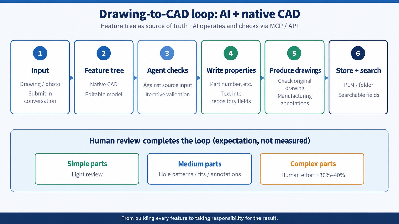
Figure 2. Proposed Drawing-to-CAD loop. Review-effort figures in the original illustration express expectations, not test results.
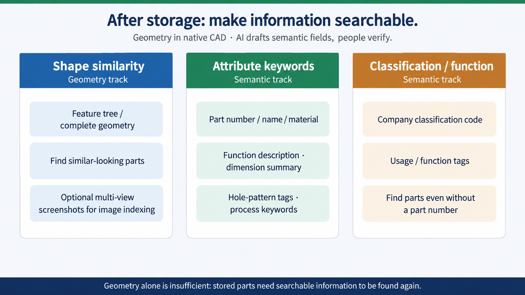
Figure 3. Retrieval can combine shape similarity, property keywords, and functional/classification information.
3. Human review remains; its work may change
The question is what an engineer must do and how much effort it takes. A manual reconstruction requires reading the drawing, building features, verifying dimensions, producing drawings, filling properties and archiving the result.
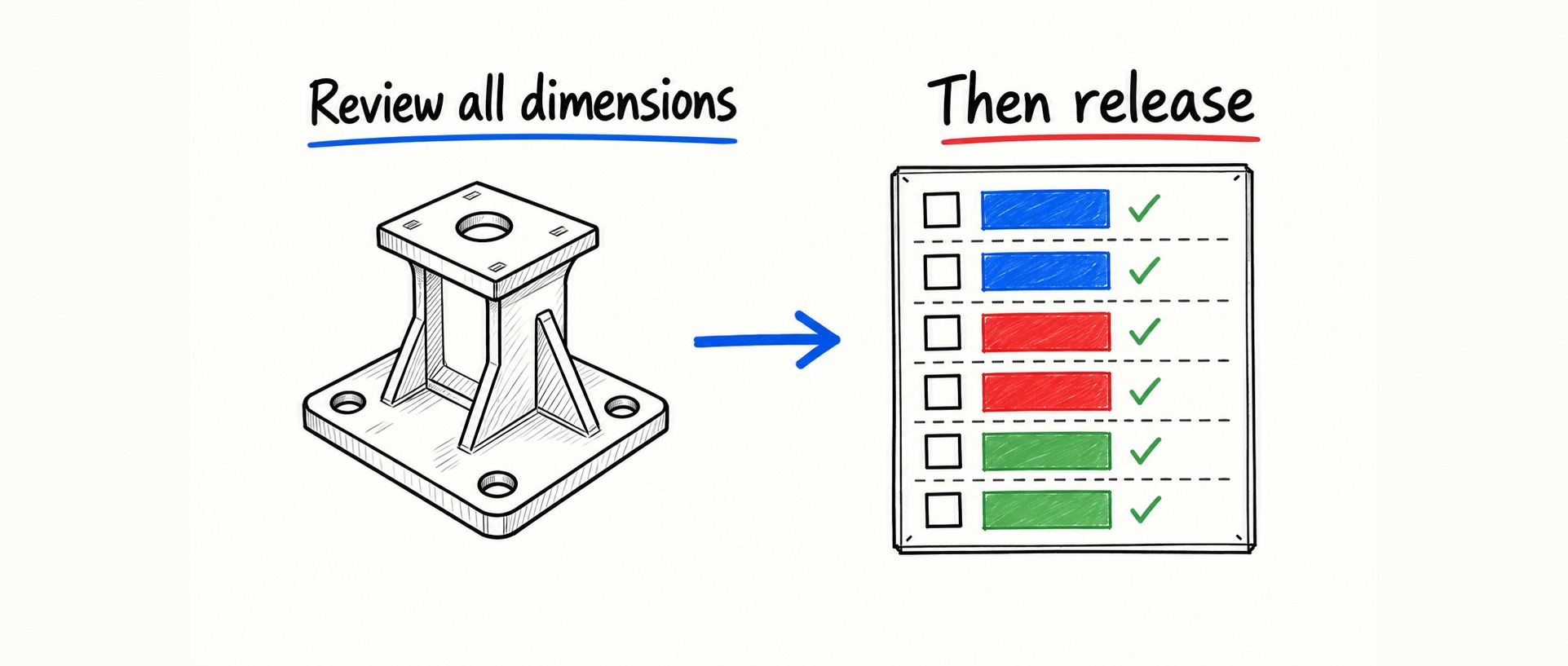
My original expectation distinguishes three broad situations. A simple, fully documented part with conventional features might need relatively light review. A moderately complex part may concentrate review on critical holes, mating surfaces and annotation consistency. For complex parts, I proposed that human effort might eventually fall to approximately 30%–40% of a fully manual workflow, focusing on dimensions and fit, missing features, process information and sign-off. Incomplete source drawings, unclear cast or sheet-metal geometry, and safety-critical dimensions require more review, not forced release to meet an automation target.
Those percentages are not measured data. They are a hypothesis about an AI-drafts / engineer-finishes architecture and need validation on representative work. The review share increases with complexity and incomplete inputs. A partial result cannot be treated as a finished deliverable.
A minimum review should ask:
- Can dimensions be changed through the intended feature history, and does the model rebuild?
- Do properties and filenames match the source?
- Are functional descriptions, dimension summaries, hole-pattern tags and classification codes usable?
- Do the drawing's critical annotations match the original?
- Are archive location, permissions and revision rules correct?
The engineer's responsibility moves from creating every operation manually toward verifying and releasing an accountable result.
4. The architectural position
I consider this a workflow worth implementing and testing: editable features, managed properties, reconciled drawings and traceable files. It provides a practical way to evaluate reverse reconstruction within the forward design process.
As models improve, the loop may become faster and require less correction. The underlying organization should still be explicit: mainstream CAD as the source of truth; AI operating through available MCP/API tools; engineers responsible for verification and release. A stronger generator alone does not resolve unmanaged deliverables or missing revision history.
The proposal is therefore a closed workflow built on established CAD practice with AI assistance. Its success should be measured by usable handover and controlled revision, as well as by the initial geometry.
Related: from STEP to a parametric model and verification for reliable CAD agents.
Illustrations are conceptual, not screenshots from a new product test. The English edition uses separately localized English illustrations with matching captions.
Sources & further reading
- Build Your Own Fusion Add-ins with the Fusion MCP ↗Source region: International
- CAD Arena research report ↗